Thermal Management System Overview
What are the detailed functions of the thermal management system (TMS)? To put it simply, it is mainly about cooling and heating. The main functions of the thermal management system on XPeng P7 mainly include:
1) The air-conditioning thermal comfort system, mainly includes air-conditioning heating, cooling, dehumidification, front defogging, interior temperature and intelligent adjustment of air circulation, etc.
2) The battery heating and cooling system, uses a four-way reversing valve and two three-way proportional valves to realize the series and parallel connection of the battery and motor circuits, thereby realizing waste heat recovery and medium-temperature heat dissipation of the battery.
◆ At high temperatures, the battery heat exchanger is relied on and the refrigerant is used to force-cool the battery.
◆ At medium temperature, the four-way reversing valve is used to connect the battery circuit and the electric drive circuit in series. The front-end low-temperature radiator dissipates heat, which can
save the power consumption of the electric compressor.
◆ At low temperatures, the three-way proportional valve is relied upon to short-circuit the low-temperature radiator. The battery and motor circuits are connected in series, and the waste heat of the motor is recovered to keep the battery warm.
◆ At ultra-low temperatures, the three-way proportional valve is used to heat the battery circuit through a water heat exchanger, to quickly warm up the battery.
3) The electric drive cooling system relies on an electric water pump to dissipate heat to the motor controller and electric motor through a low-temperature radiator.
4) For heat dissipation of XPU and large-screen host, the motor water pump is turned on based on the temperature and temperature rise rate, and a part of the flow is diverted from the motor circuit to the water-cooling plate of XPU and large-screen host for cooling, and the heat is dissipated through a radiator or bypass.
5) The water replenishment and exhaust system, the expansion kettle is connected to the battery, motor, and heating circuit to replenish water for the three circuits respectively. The battery and electric drive circuit share a water separator for exhaust, and the heating circuit uses a water separator for exhaust.
6) In the air quality management system, the PM2.5 sensor constantly monitors the air quality and displays it on the large central control screen, and then intelligently turns on the air conditioner to filter the air; in addition, the plasma generator performs sterilization, dust removal and air purification; the AQS sensor performs exhaust gas protection.
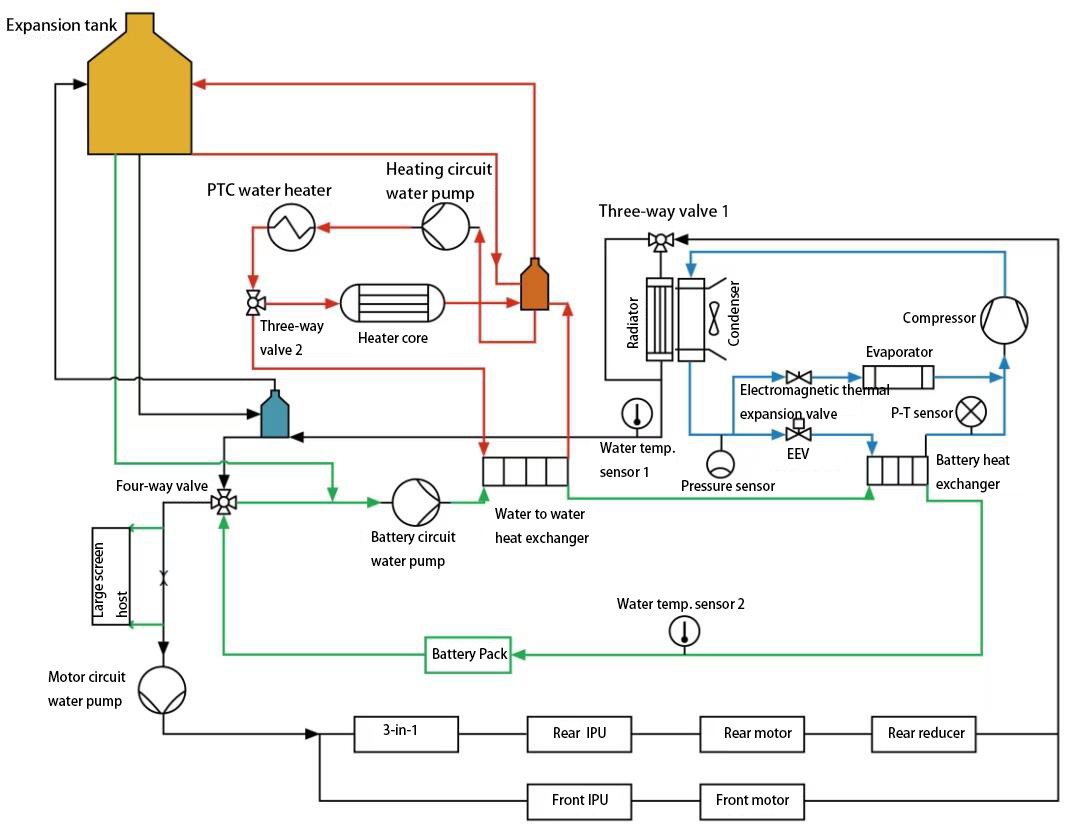
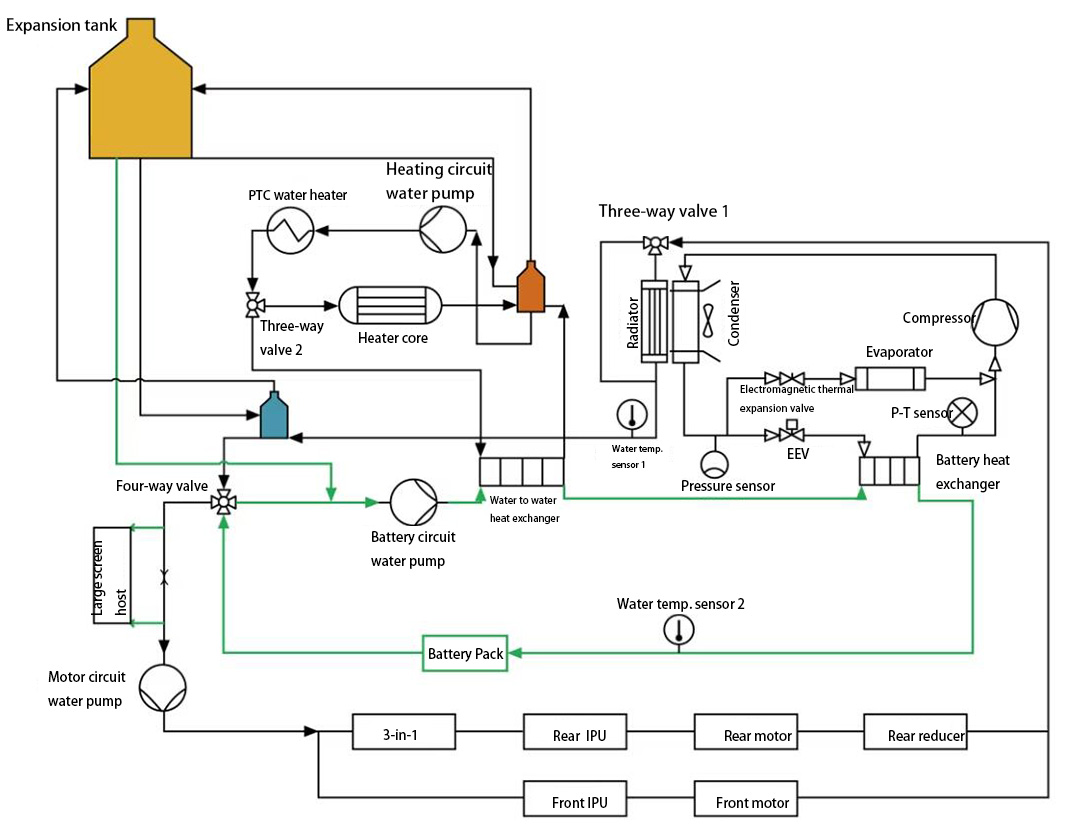
The water channels of the TMS are connected. Through the three-way and four-way water valves, series and parallel modes are realized. The block diagram of the entire thermal management system is shown in the figure below.
Fig. 1 thermal management system of XPeng P7
Control Strategies for Thermal Management System Components
Figure 1 shows the components included in the TMS. What is the control strategy for these individual components?
1) Motor circuit water pump, 60W, PWM control
The water pump will be turned on in the following cases:
◆at the time when the electric drive system has heat dissipation requirements;
◆during heat recovery;
◆at the time when the battery has an LTR cooling request;
◆When the XPU or large screen is turned on, the water pump is also turned on.
2) Battery circuit water pump, 60W, PWM control
Its operation strategy is as follows:
The water pump turns on when there is a heating or cooling request from the battery.
When there is a large the temperature difference inside the battery and thermal balance is required, the water pump is turned on.
3) Heating circuit water pump, 20W, 100Hz PWM fixed frequency control
The water pump will be turned on in the following cases:
◆ at the time when there is a heating request from the air conditioner;
◆ when there is a request for battery heating;
◆ when there are air conditioning heating requests and battery heating requests at the same time;
◆ when the left and right dual temperature zones are turned on;
◆ In the defogging mode, if the PTC needs to be turned on, the water pump will be turned on.
4) PTC, Positive Temperature Coefficient
PTC is the abbreviation of Positive Temperature Coefficient, which means positive temperature coefficient resistance, or PTC thermistor for short. Its resistance value increases stepwise as the temperature increases.
The characteristic of this method is that the power is less affected by the water temperature. The operating voltage range is 350V ~ 450V, using LIN network communication. The air conditioning controller only needs to send a power request signal to the heater, and the heater will work according to the specified power request. The maximum water temperature heated by PTC is 65℃.
PTC control logic: When the air conditioner or battery pack sends a heating request, the PTC is turned on, and the heating power of the heater is determined based on the external environment and the heating demand of the indoor air conditioner.
Specific Control Strategies for Thermal Management Functions
In the first part, the functional description of the entire TMS of XPeng P7 was listed. Next, we carefully analyze how these functions are coordinated through various components.
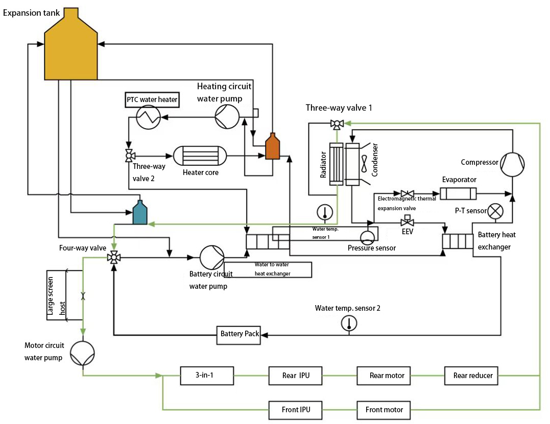
1) The control principle of motor cooling system
Motor cooling is controlled by VCU. The VCU determines the temperature of a certain component in the motor circuit. If the temperature is too high, the motor cooling starts, adjusting water pump speed and electronic fan speed in the motor circuit, and the HVAC adjusts the position of three-way proportional water valve 1 to the radiator.
Its opening temperature value: When the motor temperature is higher than 75℃, IPU is higher than 45℃, DCDC is higher than 60℃, and OBC is higher than 50℃, the motor cooling system is opened.
The entire cooling circuit is: motor circuit water pump → motor system → three-way proportional water valve 1 → radiator/bypass → four-way reversing water valve → motor circuit water pump.
Fig. 2 The control principle of motor cooling system
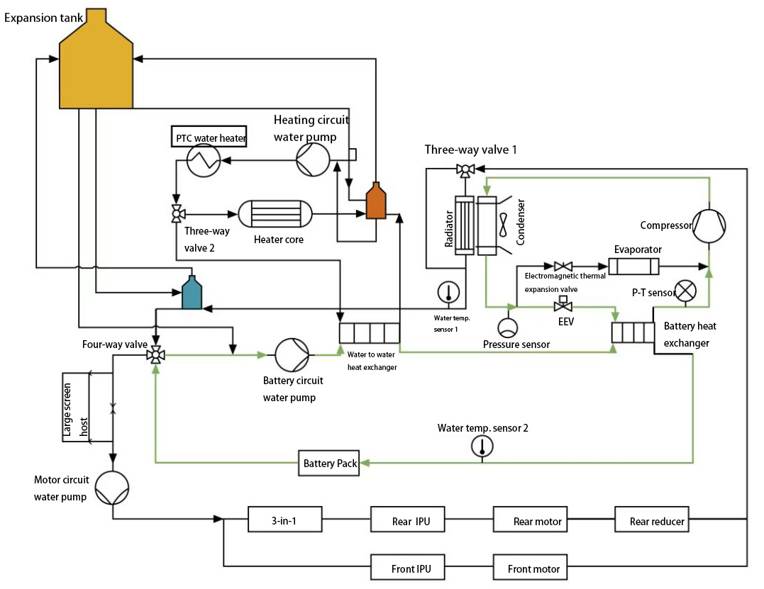
2) Battery cooling control principle
◆ Battery cooling mode 1 - in charging scenario
In this mode, the BMS determines the battery cooling needs, the VCU determines whether the battery cooling conditions are met, and the HVAC combines the ambient temperature, battery circuit water temperature, and motor circuit water temperature to determine
the use of electric compressor cooling, thereby driving the water valve and compressor, and sending water pumps and fans requests.
The cooling circuit is: compressor → condenser → electronic expansion valve (EEV) → battery heat exchanger → compressor.
◆ Battery cooling mode 2 - in driving scenario
In this mode, the VCU determines whether the conditions for battery cooling are met. HVAC combines information such as ambient temperature, battery circuit water temperature, motor circuit water temperature, etc. to determine whether to use compressor cooling, then driving the water valve and
electric air conditioning compressor, and issues requests for water pumps and fans.
The cooling circuit is: battery circuit water pump → power battery → water-to-water heat exchanger → battery heat exchanger.
Fig. 3 The control principle of battery cooling system
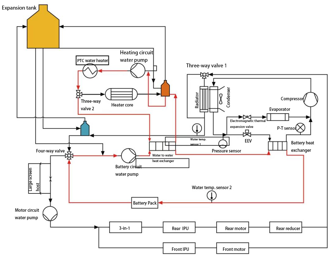
3) Battery heating control principle in charging mode
The BMS determines whether there is a need for heating based on the battery status - the VCU sends the high-voltage system status based on the vehicle status - the HVAC calculates the battery's required water temperature, and turns on the PTC and water pump for heating.
The cooling circuit includes two, one of which is: battery circuit water pump → water to water heat exchanger → battery heat exchanger → power battery pack → four-way reversing water valve → battery circuit water pump. The second one is the heating circuit water pump → water heating PTC → three-way valve 2 → water-to-water heat exchanger → heating circuit water pump.
Fig. 4 The control principle of battery heating system in charging mode
4)The control principle of battery thermal balance
When thermal shock occurs, a battery water pump needs to be opened to balance battery heat. The conditions that cause thermal shock mainly include the following two types:
◆ The difference between the maximum temperature and the minimum temperature of the battery cell is too large
◆ The difference between the battery circuit water temperature and the highest/lowest temperature of the battery is too large
The cooling circuit is: battery loop water pump → power battery pack → water-to-water heat exchanger → battery heat exchanger → battery loop water pump.
Fig. 5 The control principle of battery thermal balance
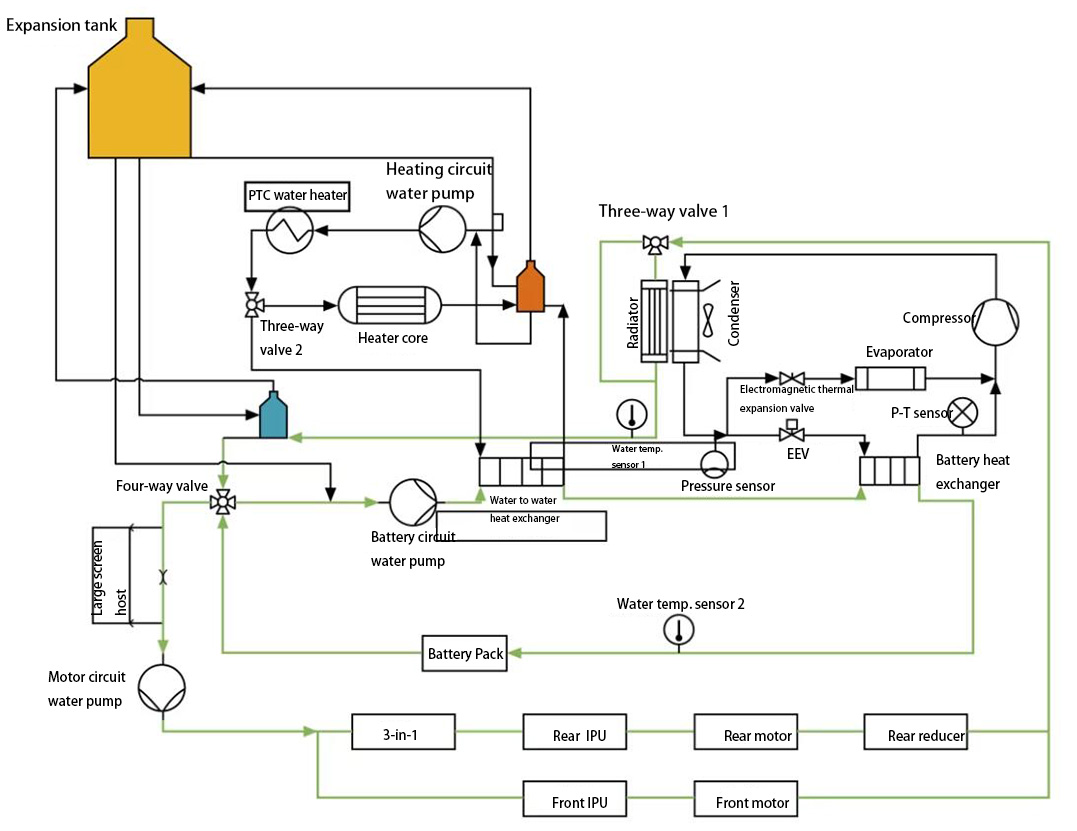
5) The control principle of battery LTR cooling and motor waste heat recovery system
This includes three parts, namely battery LTR cooling, battery pre-cooling, and motor waste heat recovery.
◆ The battery LTR cooling: at ambient temperature below 25℃, when the battery temperature is high, switch the position of the four-way reversing water valve, connect the battery circuit and the motor circuit in series, and use the radiator to dissipate battery heat, more energy saving.
◆ Battery pre-cooling: When the battery temperature is about to reach the cooling requirement temperature, use the radiator to cool the battery in advance.
◆ Motor waste heat recovery: It can be used to recover the heat generated by the motor, which is usually wasted during the operation of the vehicle. When the motor circuit water temperature is higher than the battery circuit water temperature by a certain value, it will be used to heat the battery, so that the battery is at a suitable operating temperature to achieve the purpose of energy saving.
The cooling circuit is a four-way reversing water valve → motor circuit water pump → motor system → three-way proportional water valve 1 → radiator/bypass → four-way reversing water valve → battery loop water pump → water-water heat exchanger → battery heat exchange device → power battery → four-way reversing water valve.
Fig. 6 The control principle of battery LTR cooling and motor waste heat recovery system
Related Reading:
Detailed Analysis of BYD's Electric Vehicle Heat Pump Air Conditioning Technology