The
electric vehicle ac compressor can be mainly decomposed into three parts: mechanical structure, e-motor part and control system. Each of them undertakes different core functions. The professional knowledge involved is quite different.
◆ The mechanical structure of the compressor is mainly responsible for increasing the refrigerant pressure;
◆ The electric motor provides torque to drive the compression mechanism;
◆ The electronic control part is mainly responsible for communicating with the upper controller and controlling the motor operation.
This article will introduce the key points of the
e-compressor design based on the above-listed three aspects.
1. Mechanical Structure for Compression
Electric scroll compressors are recognized by the industry as the most ideal electrically driven air conditioning compressors for electric vehicles.
1.1 Profile Design & Modification
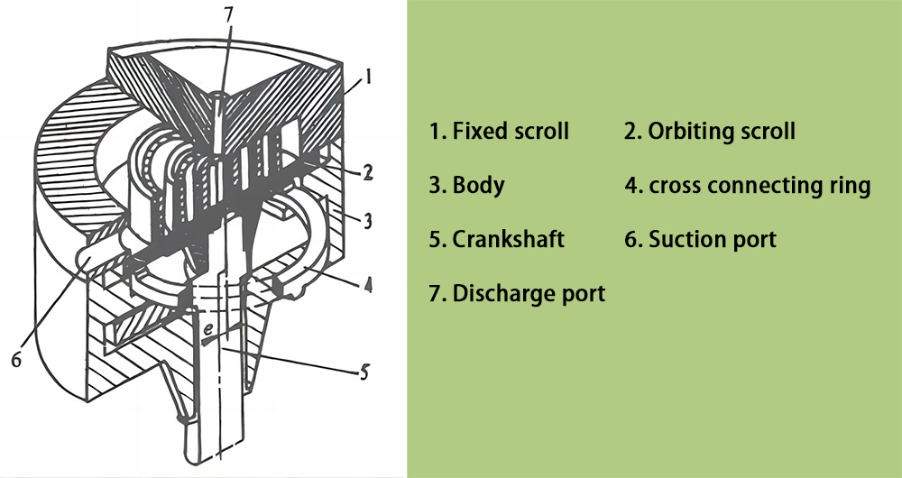
The spiral structure of the scroll is called the “Profile”.
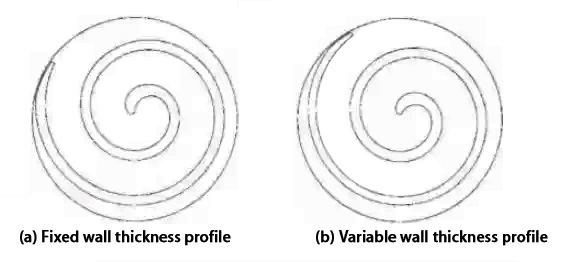
At present, the profiles used in electric scroll compressors are roughly divided into two types: fixed wall thickness and variable wall thickness.
◆ The
fixed wall thickness profile means that the wall thickness from the inner ring of the scroll wrap to the outer ring is a constant value. It is with a simple structure, low design difficulty, low cost and easy to process;
◆ The wall thickness of the
variable wall thickness profile gradually decreases from the inner ring to the outer ring of the scroll wrap. It can reduce the scroll weight to a certain extent, and enhance the operation stability, conducive to realizing lightweight design of compressor.
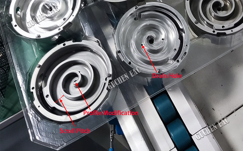
Profile design is the key technology for the design of fixed and orbiting scrolls of electric scroll compressors, and it is also the core part of the compression mechanism, because it determines the displacement. The fixed and orbiting scrolls adopt the same theoretical line design, and the circular involute design is more commonly used. The pitch, wall thickness, scroll wrap height, and number of rings are all basic design parameters. At present, the compressor displacement is mostly changed by adjusting the scroll wrap height.
Profile modification: Limited by the diameter of the machining tool, during the processing of scroll wrap composed of a single profile, the machining tool and the profile of the scroll wrap will interfere, causing adverse effects. Therefore, the scroll profile needs to be modified. Profile modification affects exhaust and production efficiency. At present, the common profile modification methods mainly include: direct truncation modification, double arc modification, linear arc modification, multi-segment arc modification, quadratic curve modification and trigonometric function modification, etc. Among them, double arc correction is the simplest, most effective and feasible method. It is also a method commonly used in
current electric scroll compressor products.
1.2 Materials and Surface Treatment Processes
Due to lightweight design requirements, in addition to the motor, crankshaft and bearings, the casing and fixed and orbiting scrolls are all made of aluminum alloy.
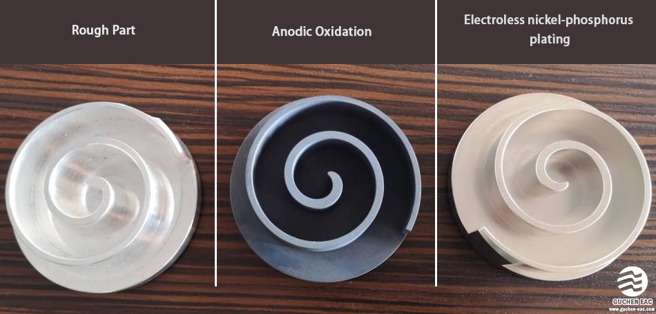
The surface coating of the scroll is also a core point that affects the compressor service life. In order to meet the requirements of high RPM and high wear resistance, the orbiting scroll should be done surface treatment to enhance the hardness.
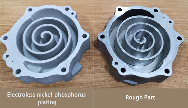
Anodic Oxidation (anodization) and nickel plating are two commonly used surface treatment processes. Considering bonding strength, surface wear resistance, line sealing efficiency, etc., the mainstream method in the industry is Electroless nickel-phosphorus plating.
The mature chemical tin plating technology can also be used on the fixed scroll. Its purpose is to protect the base material of the scroll, and provide effective cold start protection. Placing a lubricating tin plating layer on the surface of the base material can reduce noise and its friction loss, thereby extending the service life of the compressor.
The scroll design should also consider resistance to liquid hammering. Since the liquid is almost incompressible, by setting a drain hole at a specific position, when a large amount of liquid exists, the high pressure will be released through the drain hole to prevent compressor failure.
1.3 Orbiting Scroll Anti-rotation Mechanism
The anti-rotation mechanism is one of the important parts of the electric scroll compressor. Its structural parameters directly affect the compressor performance.
During the scroll compressor operation, the tangential force acting on the orbiting scroll generates a rotational moment that causes the orbiting scroll to rotate around the eccentric line of the main shaft (center line of the mainshaft crank pin). This rotational moment destroys the normal operation of the scroll compressor.
Utilizing structural principles, an anti-rotation mechanism is used to limit the rational motion of the orbiting scroll, making the orbiting scroll to perform rotational and translational motion, ensuring the correct engaging of the fixed and orbiting scroll wrap, thus enabling the scroll compressor to work stably.
Anti-rotation Mechanism
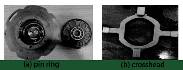
There are many structural forms of anti-rotation mechanisms, such as crosshead, spherical coupling, pin and hole couplings, steel ball and ring groove combination couplings, crank pins, etc.
Crosshead mechanism: The combination of a main shaft with a crank pin and a crosshead mechanism is used to realize the planar motion and power input of the orbiting scroll. It is currently the most commonly used structural form in
fully-enclosed electric air conditioning compressors. The anti-rotation mechanism is placed between the orbiting scroll and the bracket body. A pair of convex keys match the keyway of the orbiting scroll, and the other pair matches the keyway on the bracket body.
In-depth research on the anti-rotation mechanism can make the movement of the orbiting scroll more stable and reliable; it is beneficial to the compressor noise reduction and energy saving; it can increase the service life of the scroll compressor and improve its working efficiency.
2.Electric Motor Technology
In order to meet the technical requirements of miniaturization and high efficiency,
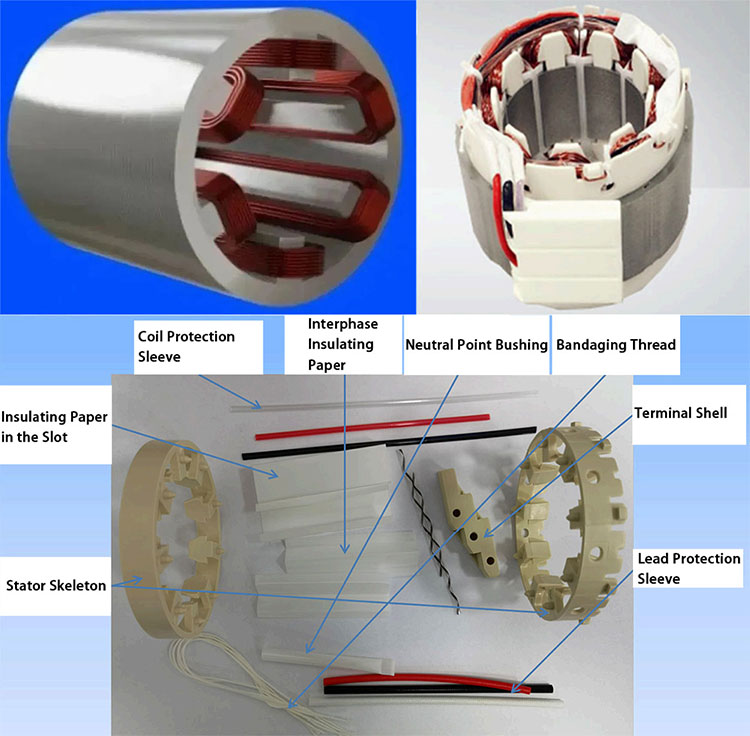
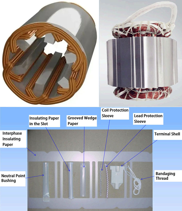
electric ac compressors are driven by permanent magnet synchronous motors at present. According to the motor winding form, the stator has two structural forms: concentrated winding and distributed winding.
Concentrated winding
Distributed winding
The stator uses special fluorine-resistant enameled wire to ensure long-term reliability of the motor when soaked in refrigerant and lubricating oil environments, and has an insulation performance of greater than 500 MΩ; Commonly used magnetic poles of rotors include 4-pole, 6-pole, and 8-pole structures.
3. Control Technology
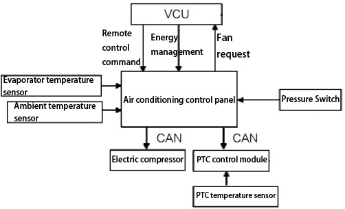
From an electrical perspective, the air conditioning system mainly consists of the following parts: air conditioning controller, compressor and thermodynamic system, compressor motor and its controller, communication module, and temperature and pressure sensor. As shown below.
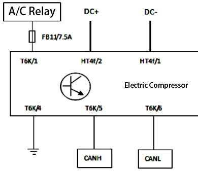
The electrical part of the vehicle air conditioner is divided into two parts, the high-voltage part and the low-voltage part. As shown in the figure below, DC+ and DC- are high-voltage power supplies that are directly connected to the compressor motor controller. The "air conditioning relay" in the picture is the power switch of the air conditioning controller.
Logic
The low-voltage part of the air conditioner is controlled by VCU. VCU controls the on and off of the entire air conditioner by controlling the 12V power circuit "air conditioner relay"; it transmits command information to the air conditioner controller through the CAN bus and sets the operating temperature target value;
The air-conditioning controller feeds back air-conditioning working status information to the VCU, including strong current circuit switch on and off information, compressor pressure, and compressor inlet and outlet temperature. The high-voltage power supply of the A/C compressor comes from the vehicle-mounted DC-DC converter. The air-conditioning controller controls the on and off of the contactor on the power circuit through the contactor trigger port, and then controls the working status of the compressor motor.
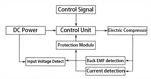
Working principle diagram of the control system
◆ Suitable for working in low temperature -20℃ and high temperature 125℃ environments.
◆ Meet the EMC requirements of no less than Level 3 standards.
◆ The selection of electronic components requires products with vehicle certification.
◆ It has good high-voltage electrical safety and meets the electrical strength for working at an altitude of 4000m.
◆ The chip has enough capacity to meet the underlying software development hardware environment of UDS and Bootloader.
◆ The communication method adopts CAN or LIN communication.
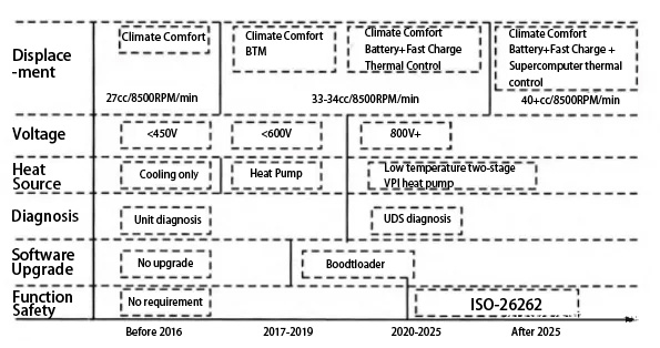
Electric compressor technology roadmap


